In Twelve Small Injectors Instead of Six Big Ones I explained why this car runs two injectors per cylinder. I finished by saying the handover between primaries and secondaries was the part I knew least about, and where I’d expect the problems to live.
This is the follow up. How the Emtron KV12 actually stages twelve injectors, every table that controls it, and one thing I had described wrongly.
Each section is marked. Verified means it comes straight from the calibration or the logs. Theory means it is my reasoning or arithmetic, not something I have measured.
Configuration
Status: Verified
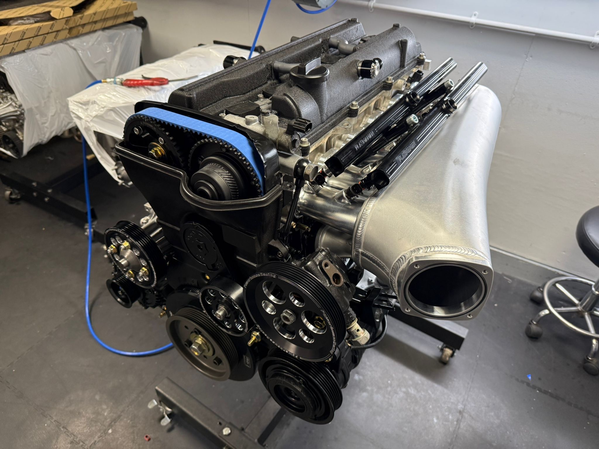
- 2JZ-GTE VVTi, 3,353 cc, flex fuel
- Plazmaman intake manifold, twin fuel rails mounted on the runners
- Twelve CP1000 injectors, rated 1,000 cc/min at 3 bar, high impedance
- 1:1 rising rate regulator, fuel pressure sensor fitted
- Three Walbro 485 pumps
- Emtron KV12, every injector on its own channel
How Emtron does it
Status: Verified
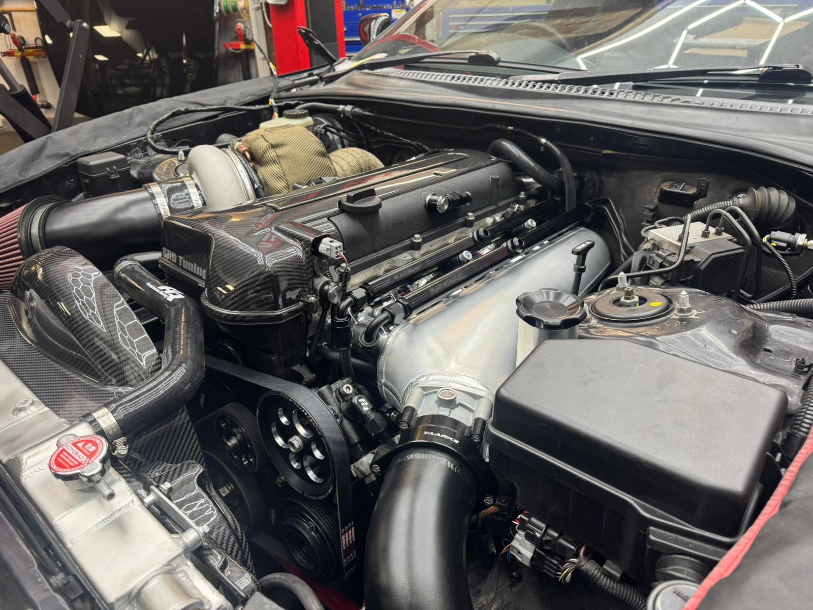
Staging is an injection mode, not an add on. The KV12 offers seven:
- 0: Off
- 1: Sequential
- 2: Sequential/Staged Sequential (this car)
- 3: Sequential/Staged Group
- 4: Non Sequential
- 5: GDI Sequential
- 6: GDI Sequential/Staged, primary GDI and secondary port
Mode 2 fires the secondaries sequentially as well, each one timed to its own cylinder. Mode 3 groups them, which is what you would use on an ECU without enough channels. With twelve dedicated outputs there is no reason to group anything.
Once staging is enabled, the secondaries get their own setup page, and it mirrors the primary one line for line:
| Setting | Primary | Secondary |
|---|---|---|
| Reference injector size | 1,190 cc/min | 1,190 cc/min |
| Reference static fuel pressure | 400 kPa | 400 kPa |
| Injection timing | End of injection | End of injection |
| Nozzle reference pressure | Manifold pressure | Manifold pressure |
| Fuel pressure correction | On, sensor fitted | On, sensor fitted |
| Injector max duty clamp | 95% | n/a |
| Minimum effective pulse width | 0.200 ms | n/a |
| Staging rpm lockout | n/a | 1,000 rpm |
| Staging ON, balance table above | n/a | 5.0 |
| Staging OFF, balance table below | n/a | 5.0 |
Fuel pressure correction being on with a sensor fitted matters more than it looks. The ECU is not trusting the regulator to hold 400 kPa across the injector. It measures the differential and corrects flow for it. A 1:1 regulator gets you close, but close is not the same as measured.
The channel map
| Channel | 1 | 2 | 3 | 4 | 5 | 6 | 7 | 8 | 9 | 10 | 11 | 12 |
|---|---|---|---|---|---|---|---|---|---|---|---|---|
| Primary, cylinder | 1 | 2 | 3 | 4 | 5 | 6 | – | – | – | – | – | – |
| Secondary, cylinder | – | – | – | – | – | – | 5 | 6 | 3 | 2 | 1 | 4 |
Channels 7 to 12 do not run 1 to 6. That is fine, as long as the map matches the wiring. Get one wrong and a secondary fires on the wrong cylinder’s timing. You will not see that on a single wideband, because the total fuel is still right. The only proper check is firing each channel individually.
Characterising the injector
Status: Verified
The injectors are CP1000s, rated 1,000 cc/min at 3 bar. Scaled to the 400 kPa this car runs across the injector, that is about 1,155 cc/min each, roughly 13,860 cc/min across all twelve, the equivalent of six 2,310 cc injectors.
The calibration doesn’t use 1,155. Its reference size is 1,190 cc/min at 400 kPa, taken from CP Fuel and Race data rather than scaled from the headline rating. The square root rule is a good approximation, not a measurement. Where the manufacturer has measured the injector at your pressure, use their number.
The dead time table is identical for both banks, which is correct for identical injectors:
| Diff pressure vs supply | 8 V | 10 V | 12 V | 14 V | 16 V |
|---|---|---|---|---|---|
| 300 kPa | 2.609 | 1.675 | 1.240 | 0.960 | 0.756 |
| 400 kPa | 3.053 | 1.892 | 1.353 | 1.057 | 0.836 |
| 500 kPa | 3.659 | 2.086 | 1.484 | 1.125 | 0.910 |
Dead time rises with pressure and falls with voltage. The solenoid has to pull the pintle open against the fuel pressure, and a higher supply voltage builds current in the coil faster. On a running car at 14 V and 400 kPa, the first 1.057 ms of every pulse is dead time: the injector is energised but not yet delivering its rated flow.
Both banks run saturated drive, which is right for a high impedance injector. Peak and hold is for low impedance injectors that need a current limit.
Flex fuel is handled underneath
The fuel model works in mass, so the ECU needs to know two things about whatever is in the tank: how much air it needs to burn completely, and how dense it is.
| Ethanol | 0% | 10% | 20% | 30% | 40% | 50% | 60% | 70% | 80% | 90% | 100% |
|---|---|---|---|---|---|---|---|---|---|---|---|
| Stoich AFR | 14.70 | 14.13 | 13.56 | 12.99 | 12.42 | 11.85 | 11.28 | 10.71 | 10.14 | 9.57 | 9.00 |
The table is a straight line between petrol and ethanol, by volume. Strictly, stoichiometry blends by mass, not volume, so I checked it. At E85, weighting by mass gives 9.81. The table interpolates to 9.86. Half a percent, well inside what the closed loop trims absorb. Not worth correcting.
| Ethanol vs fuel temp | -20 °C | 0 °C | 20 °C | 40 °C | 60 °C | 80 °C | 90 °C |
|---|---|---|---|---|---|---|---|
| 0% | 0.773 | 0.759 | 0.745 | 0.731 | 0.717 | 0.703 | 0.690 |
| 50% | 0.800 | 0.784 | 0.768 | 0.752 | 0.736 | 0.720 | 0.710 |
| 100% | 0.825 | 0.807 | 0.789 | 0.771 | 0.753 | 0.735 | 0.720 |
One small oddity: the step from 80 to 90 °C is steeper than every other step in the table, and the 90 °C column is rounded to two decimal places. It doesn’t matter here, because the fuel in this rail never gets near 90 °C. If yours does, that column is worth a second look.
The balance table: a blend, not a switch
Status: Verified
This is the table that decides who does the work. The value is the secondary bank’s share of total fuel. Zero means primaries only. Fifty means an even split.
| MAP vs rpm | 1,000 | 1,500 | 2,000 | 2,500 | 3,000 | 3,500 | 4,000 | 4,500 | 5,000+ |
|---|---|---|---|---|---|---|---|---|---|
| 20 to 100 kPa | 0 | 15 | 20 | 25 | 30 | 35 | 40 | 45 | 50 |
| 120 kPa | 0 | 26.5 | 30 | 33.5 | 36.5 | 40 | 43.5 | 46.5 | 50 |
| 140 kPa | 0 | 38.5 | 40 | 41.5 | 43.5 | 45 | 46.5 | 48.5 | 50 |
| 160 to 180 kPa | 0 | 50 | 50 | 50 | 50 | 50 | 50 | 50 | 50 |
| 200 to 240 kPa | 50 | 50 | 50 | 50 | 50 | 50 | 50 | 50 | 50 |
Read the top row. At 1,500 rpm in vacuum, the secondaries supply 15 percent. By 2,000 it is 20. The share climbs 5 points every 500 rpm until it reaches an even split at 5,000.
Add boost and the ramp gets steeper. At 140 kPa the secondaries are already at 38.5 percent by 1,500 rpm, and from 160 kPa upwards it is an even split everywhere above 1,000.
Which means I described this wrongly. In Twelve Small Injectors I wrote that at idle, around town, and at any low load, only the primaries fire. The table says otherwise. Around town at 2,000 rpm, a fifth of the fuel is coming from the secondaries. Only idle runs on primaries alone.
This isn’t staging in the on/off sense. It’s a blend with a floor.
Where the switch actually is
Two settings decide when the secondaries are allowed to fire at all.
The staging rpm lockout holds them off below 1,000 rpm, whatever the table says. Above that, staging comes on when the interpolated balance value rises above 5.0 and goes off when it falls below 5.0.
The table goes from 0 at 1,000 rpm to 15 at 1,500. Interpolating between them, it crosses 5 at about 1,170 rpm, at every MAP up to 100 kPa. That is the real staging point for normal driving.
And because ON and OFF are both 5.0, there is no hysteresis. The same threshold switches the bank in and out. Sitting at 1,170 rpm, the secondaries could in principle toggle on every fluctuation of engine speed.
What keeps idle clean is the idle target. I moved it to 950 rpm, under the lockout, so at idle the secondaries are never asked to fire.
What the secondaries are being asked to do
Status: Verified
The whole reason for twelve injectors is to keep pulse widths out of the region where an injector stops being predictable. So it’s worth asking what pulse width the secondaries actually see at light load.
I haven’t measured this directly. This is arithmetic from the fuel model, assuming 80 percent volumetric efficiency, 30 °C charge and lambda 1:
| Condition | All fuel through one injector | Secondary at 5% | Secondary at 15% | Secondary at 20% |
|---|---|---|---|---|
| 40 kPa, E85 | 1.36 ms | 0.07 ms | 0.21 ms | 0.27 ms |
| 40 kPa, petrol | 0.95 ms | 0.05 ms | 0.14 ms | 0.19 ms |
| 60 kPa, E85 | 2.05 ms | 0.10 ms | 0.31 ms | 0.41 ms |
At 1,500 rpm in light cruise, the secondaries sit right on the 0.200 ms minimum on E85 and below it on petrol. At the moment staging switches on, with the balance at 5 percent, they are being asked for something like a third of the minimum.
That is exactly the region Twelve Small Injectors says staging exists to avoid. The primaries are comfortable. The secondaries are not.
The calibration has no short pulse correction either. For very short pulses, the ECU is converting fuel mass to time using dead time and a straight line slope, and a straight line is exactly what an injector stops being down there.
What the KV12 does with a request below its own minimum, whether it clamps up to 0.200 ms or drops the pulse, I don’t know. Either way, the secondary delivery in that window is not what the model thinks it is.
What the logs say
Status: Verified
Lambda control is good through the staging region. On the road the handover is transparent. I can’t feel it, and the wideband doesn’t show a step.
Which looks like it contradicts the section above. I don’t think it does. Maybe we can refine this in the future.
Why it holds up anyway
Status: Theory
Two reasons, and I suspect both apply.
First, the error is a percentage of a small number. If a secondary at 15 percent share delivers 20 percent more or less than asked, the cylinder sees a 3 percent error in total fuel. That is inside what closed loop trims correct without anyone noticing.
Second, the closed loop may be doing exactly that. Good lambda control in a region where the open loop model is weakest doesn’t prove the model is right. It may only prove the trims are working. The way to tell the difference is to log the trims, not lambda, through the 1,170 to 2,500 rpm band. Emtron logs the effective and actual pulse width of both banks separately, so the secondary pulse widths can be checked against the estimates above.
Where the injectors are, and why it barely shows
Status: Theory
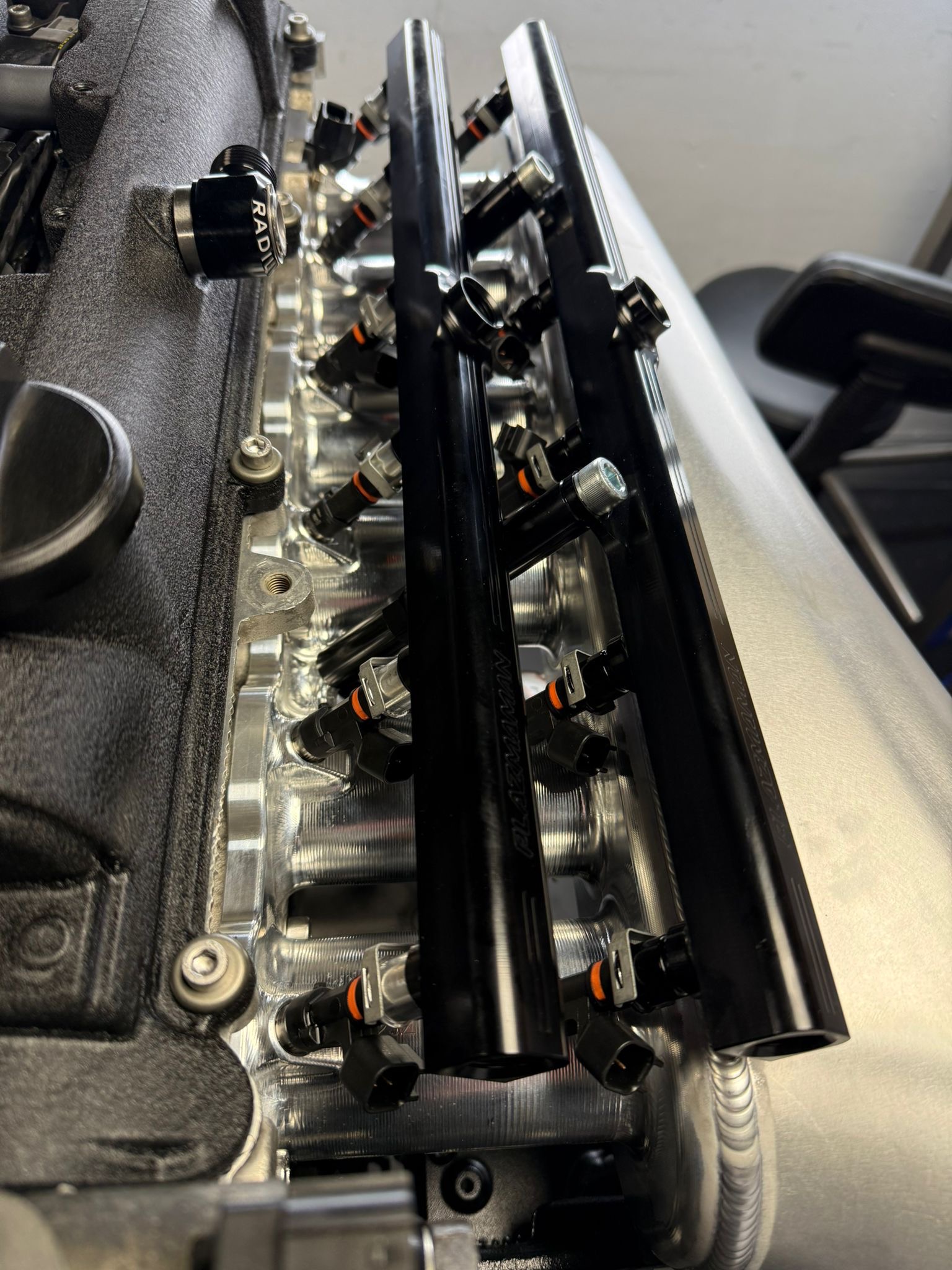
Both rails sit on the runners, one row close to the head and the other further out along the runner. So the two banks do not take quite the same path to the valve. Fuel from the outer row travels further, wets more runner wall, and arrives slightly later. Calibrating a handover between two injector positions means accounting for two transport paths.
On this manifold the gap between the two rows is short, far shorter than on layouts that put the secondaries up in the plenum or the intake tract. I’d expect the difference in transport and wall wetting to be small. It also matters least where the secondaries carry the smallest share of the fuel, which is exactly the light load region above. That is probably part of why the handover is transparent, but I haven’t measured it.
What I’d change
Status: Working conclusion
Nothing is broken, so none of this is urgent. But the calibration is relying on the trims in a region where it doesn’t need to.
- Bring the secondaries in later and bigger. Six 1,000 cc primaries have far more than enough capacity to carry light cruise on their own. Holding the secondaries at zero through light load, and bringing them in where their share gives a pulse width comfortably clear of the minimum, means they never operate in the bottom of their range.
- Split ON and OFF. Identical thresholds mean no hysteresis. A gap between them stops the bank chattering at the switch point.
- Mind the margin at idle. 950 rpm against a 1,000 rpm lockout is 50 rpm of margin. Anything that lifts the idle above 1,000, such as a higher cold idle target, an idle flare or load compensation, brings the secondaries in at the smallest pulse widths in the table.
- Add short pulse data if the ECU will take it. It is the one piece of the injector model the calibration doesn’t have, and it matters most in exactly the light load region above.
The principle
Staging solves a pulse width problem. The balance table can quietly give it straight back by handing the secondaries a sliver of fuel at light load.
So when you set one up, don’t only check that lambda is clean through the transition. Work out the secondary pulse width at the first non zero cell in the table, and check it against the injector’s minimum. If it is below, the ECU is guessing and the closed loop is covering for it.
Every number here is specific to this car, these injectors and this manifold. The data is not transferable, but the principle is.
Why the car has twelve injectors in the first place, and the flow arithmetic behind them, is in Twelve Small Injectors Instead of Six Big Ones. What the fuel system makes possible on E85 is in What E85 Actually Buys. Full specification is on the Supra project page.
If you run a staged setup on an Emtron and know what the KV12 does with a request below the minimum effective pulse width, I’d like to hear it.