One of the recurring themes with the Supra has been that once the obvious problems are fixed, the remaining calibration work becomes less about making something work and more about understanding why it behaves differently under different conditions.
The VVT-i control on the 3.4-litre 2JZ-GTE has been a good example.
The car wasn’t suffering from some catastrophic VVT-i failure. The cam moved, the ECU controlled it and, once everything was properly hot, it could track the requested position extremely accurately.
What caught my attention was that it wasn’t equally good all the time.
The further I dug into the logs, the clearer it became that oil temperature was having a significant effect on what the VVT-i controller needed to do.
This is the journey from a conventional PID setup, through feed-forward changes and temperature-dependent duty-cycle limits, to the new oil-temperature-compensated PID strategy we’re about to test.
The starting point
The VVT-i system is controlled by the Emtron KV12 using closed-loop PID control.
In simple terms, the ECU has a requested inlet cam position and an actual measured cam position. The difference between those two is the VVT Target Error.
The PID controller then uses three components to correct it:
- Proportional (P) reacts to the current error.
- Integral (I) reacts to error accumulated over time.
- Derivative (D) reacts to how quickly that error is changing.
There is also a Feed Forward duty cycle. Rather than asking the PID to generate the entire solenoid command itself, feed-forward provides a baseline duty cycle that should put the VVT mechanism somewhere close to where it needs to be. PID then deals with the remaining error.
That distinction became important.
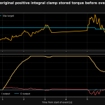
The first clue: the Integral was doing too much work
The original VVT feed-forward was around 34% DC.
Looking through the logs, the VVT system would track the target, but the Integral controller was regularly having to add substantial duty cycle.
That tells you something.
If the controller repeatedly needs Integral to provide the same correction, Integral isn’t really correcting a transient disturbance any more. It’s compensating for an inaccurate baseline.
So I increased VVT feed-forward to 41% DC.
At the same time, I reduced the VVT deadband to ±0.4°.
The deadband is simply the region around the target where the ECU stops trying to correct tiny errors. There’s no benefit in constantly moving the VVT solenoid because the cam is 0.1° away from target. That can simply introduce unnecessary activity and oscillation.
The initial results with 41% were interesting.
When fully hot, they were excellent.
When cold, they weren’t.
Oil temperature was the missing variable
Once I started analysing the VVT logs against engine oil temperature, a very obvious pattern appeared.
With the fixed 41% feed-forward, the approximate Integral correction looked like this:
| Oil temperature | Typical Integral correction |
|---|---|
| Cold | ~-7% DC |
| 80–85°C | ~-4% DC |
| 90–95°C | ~-2 to -2.5% DC |
| 96–100°C | ~-1% DC |
At approximately 96–100°C oil temperature, VVT control was exceptionally good.
One of the hot boost logs produced approximately:
| Metric | Value |
|---|---|
| Mean VVT target error | +0.04° |
| Median absolute error | ~0.4° |
| Mean Integral correction | ~-1% DC |
That is basically where I wanted it.
The feed-forward gets the system very close, the PID makes small corrections, and the actual cam follows the requested position accurately.
But look at the other end of the temperature range.
Cold, the Integral controller was approaching its -8% DC clamp.
That immediately suggested the problem wasn’t fundamentally the PID gains.
The hydraulic system itself was changing.
VVT-i is an oil-pressure-operated system
This sounds obvious once you say it, but it matters enormously to the calibration.
The Toyota VVT-i mechanism is hydraulic.
Change the oil temperature and you change the viscosity of the oil. That changes the behaviour of the solenoid and cam phaser for a given electrical duty cycle.
So why should we expect one fixed solenoid feed-forward duty to be correct at 20°C oil temperature and still be correct at 100°C?
We shouldn’t.
The logs were effectively showing us that.
This also explained why I didn’t want to start aggressively changing the P, I and D gains simply because the cold behaviour looked different.
Once the oil was properly hot, the PID was already working extremely well.
Changing a good PID to compensate for an incorrect hydraulic baseline would have been fixing the wrong thing.
The feature request to Emtron
The obvious solution seemed to be a temperature-dependent VVT feed-forward table.
Rather than:
Feed Forward = 41% DC
I wanted something conceptually closer to:
Oil temperature → appropriate base VVT solenoid duty
Potentially, the ideal implementation could eventually become a two-dimensional table using both oil temperature and engine speed.
I submitted the calibration and logs to Emtron as a feature request.
Nick Pavloski from Emtron came back with a pragmatic answer.
The requested change was unlikely to happen at this stage of the firmware development, but he suggested using the existing Min/Max Duty Cycle tables and their flexible axes to achieve what I needed.
That sent the calibration in a slightly different direction.
Using the VVT duty limits properly
The existing calibration already had temperature-dependent minimum and maximum VVT solenoid duty tables.
Originally, the minimum was essentially fixed at 10%, while maximum duty jumped from around 40% when cold to 80% once warm.
Rather than treating these purely as broad safety limits, I could use oil temperature as the flexible axis and progressively release VVT actuator authority as the oil warmed.
This isn’t exactly the same thing as temperature-dependent feed-forward.
That’s important.
Feed-forward moves the controller’s baseline operating point.
A Max DC table limits how much duty the controller is allowed to command.
Those are fundamentally different control strategies.
But I had the facility available, Emtron had recommended using it, and most importantly I could test the result objectively.
So I did.
The revised limits worked
The first useful cold-to-warm log with the revised limits was considerably better than I expected.
| Oil temperature | Mean VVT error | Median absolute error | 95th-percentile absolute error |
|---|---|---|---|
| 60–70°C, before | -1.21° | 1.2° | 3.7° |
| 60–70°C, revised limits | -0.08° | 0.3° | 0.6° |
| Above 70°C, revised limits | ~-0.09° | ~0.4° | — |
That is extremely accurate tracking.
So this wasn’t a tiny change visible only because we’d tortured the data sufficiently.
The improvement was substantial.
It also gave some useful validation to another calibration decision on the car.
I already have a warning light that remains active until engine oil exceeds 70°C. I don’t start using the car hard until that light goes out, and I also require the ZF 8HP gearbox to be above 40°C.
Previously I’d considered 90–95°C oil the point where VVT behaviour really became trustworthy.
With the revised VVT control, that changed.
By 60–70°C, the cam tracking was already extremely good.
The 70°C threshold now corresponds quite nicely with the point where the VVT system has demonstrated that it is properly under control.
But the Integral still told us something
Although actual cam tracking had improved dramatically, one thing hadn’t disappeared.
The Integral remained substantially negative during warm-up.
That means the underlying issue hasn’t magically vanished. The controller is still compensating for the relationship between fixed feed-forward duty and changing hydraulic behaviour.
The duty limits have given us a very effective workaround, but they haven’t fundamentally turned the fixed 41% feed-forward into a temperature-dependent feed-forward model.
Then I found another useful capability in EMtune.
The PID tables themselves can have a second axis.
And that axis can be Engine Oil Temperature.
That gives us another tool.
Moving from 2D to 3D PID control
Previously, each PID gain was effectively a one-dimensional table.
For example, proportional gain changed according to VVT Target Error.
Now I can retain Target Error on the X-axis and add Engine Oil Temperature on the Y-axis.
That means the controller can behave differently at 20°C oil temperature than it does at 100°C.
But there was an obvious trap here.
Just because the software gives you another axis doesn’t mean you should use it aggressively.
The hot VVT calibration was already excellent.
So the new strategy deliberately leaves the hot calibration alone.
The oil-temperature breakpoints are: 20 / 40 / 60 / 70 / 80 / 100°C
- From 80°C upwards, the original proven PID values remain unchanged.
- Below 80°C, P and I are progressively softened.
- Derivative remains unchanged across the entire temperature range.
The new Proportional table
The original hot P calibration is retained at 80°C and above. Columns are VVT Target Error; rows are engine oil temperature.
| Oil temp | -12° | -8° | -4° | -2° | +2° | +4° | +8° | +12° |
|---|---|---|---|---|---|---|---|---|
| 20°C | 1.55 | 0.95 | 0.92 | 0.90 | 0.90 | 0.95 | 1.10 | 1.25 |
| 40°C | 1.60 | 0.98 | 0.95 | 0.93 | 0.93 | 0.98 | 1.14 | 1.30 |
| 60°C | 1.70 | 1.00 | 0.98 | 0.96 | 0.96 | 1.01 | 1.18 | 1.35 |
| 70°C | 1.75 | 1.03 | 1.00 | 0.98 | 0.98 | 1.03 | 1.21 | 1.38 |
| 80°C | 1.80 | 1.05 | 1.02 | 0.99 | 0.99 | 1.05 | 1.23 | 1.41 |
| 100°C | 1.80 | 1.05 | 1.02 | 0.99 | 0.99 | 1.05 | 1.23 | 1.41 |
This isn’t a radical change.
That’s deliberate.
The proportional controller wasn’t broken.
Integral gets the bigger change
Integral is where temperature compensation potentially has more value.
The new table progressively reduces Integral gain as oil temperature falls:
| Oil temp | -20° | -10° | -3° | -1° | +1° | +3° | +10° | +20° |
|---|---|---|---|---|---|---|---|---|
| 20°C | 0 | 0.003 | 0.020 | 0.012 | 0.012 | 0.020 | 0.002 | 0 |
| 40°C | 0 | 0.003 | 0.024 | 0.015 | 0.015 | 0.024 | 0.002 | 0 |
| 60°C | 0 | 0.004 | 0.029 | 0.018 | 0.018 | 0.029 | 0.002 | 0 |
| 70°C | 0 | 0.004 | 0.033 | 0.020 | 0.020 | 0.033 | 0.003 | 0 |
| 80°C | 0 | 0.005 | 0.036 | 0.022 | 0.022 | 0.036 | 0.003 | 0 |
| 100°C | 0 | 0.005 | 0.036 | 0.022 | 0.022 | 0.036 | 0.003 | 0 |
Again, above 80°C nothing changes.
The objective isn’t to hide the fact that Integral wants to correct the baseline. Reducing I gain cannot fix an incorrect feed-forward value.
It simply stops the Integral controller aggressively accumulating correction while the cold hydraulic system is simultaneously being constrained by the temperature-dependent duty limits.
And Derivative?
I left it alone.
Every temperature row uses the existing values:
| Oil temp | Bp 1 | Bp 2 | Bp 3 | Bp 4 | Bp 5 | Bp 6 | Bp 7 | Bp 8 |
|---|---|---|---|---|---|---|---|---|
| All (20–100°C) | 0 | 2.00 | 2.40 | 2.40 | 2.40 | 2.40 | 1.60 | 0 |
There is currently no evidence that D needs temperature compensation.
Adding another variable because the software allows it is exactly how calibrations become unnecessarily complicated.
If future logs demonstrate a genuine temperature-dependent damping problem, I’ll change it.
Until then, D stays where it is.
Establishing a proper baseline
Before testing the new 3D PID, I logged the previous calibration fully warm.
That gives us something important: a benchmark.
At approximately 76–81°C oil temperature, the previous PID was already producing:
| Metric | Previous PID, 76–81°C oil |
|---|---|
| Mean VVT error | ~0° |
| Median absolute error | 0.2–0.3° |
| 95th-percentile absolute error | 0.5–0.7° |
| Time in Deadband state | ~82% of valid samples |
That’s very good.
So the new PID doesn’t get declared successful simply because a graph looks tidy.
It has to beat — or at minimum preserve — what I already have.
At 70–80°C, if the new calibration produces materially worse tracking than roughly 0.3° median absolute error, it has failed.
I’ll revert it.
Where the calibration stands now
| Parameter | Setting |
|---|---|
| Feed Forward | 41% DC |
| Deadband | ±0.4° |
| Integral clamp | ±8% DC |
| Min/Max DC | Temperature-dependent |
| P gain | Target Error × Engine Oil Temperature |
| I gain | Target Error × Engine Oil Temperature |
| D gain | Target Error × Engine Oil Temperature, currently identical at every temperature |
The important bit is that this hasn’t been developed by randomly changing numbers until the car felt better.
Each step came from something measurable in the logs:
- We saw excessive Integral correction.
- We changed feed-forward.
- That exposed a temperature relationship.
- We correlated it against oil temperature.
- We changed the available duty-cycle envelope.
- Tracking improved substantially.
- We then found that EMtune could add oil temperature directly to the PID gain tables.
Now I have a calibration specifically designed around what the data has shown us.
What happens next
The new 3D PID still needs validating.
The next useful log needs to capture the engine continuously through approximately:
- 20–40°C
- 40–60°C
- 60–70°C
- 70–80°C
- 80–100°C
Then, once properly hot, it needs some genuine loaded operation.
The channels that matter are VVT Target, VVT Position, Target Error, Solenoid Duty, PID Status and the individual P, I and D outputs.
I’m particularly interested in the transition through 60–80°C.
The previous calibration has already set a high standard there. The new strategy needs to preserve that accuracy while improving the behaviour earlier in the warm-up.
The ultimate objective isn’t a perfectly flat graph.
It’s much simpler than that.
When I ask the inlet cam to be somewhere, I want it to get there quickly, stay there accurately and do so without the PID controller having to fight the underlying system.
At around 100°C oil temperature, we’re already essentially there.
Now we’re trying to make the journey from cold oil to that operating state just as controlled.