The car was giving me inconsistent torque readings, inconsistent delivery, and downstream of both, inconsistent shifts. And on rarer occasions the car would overfuel like crazy when returning to idle. It’s done this maybe 6-8 times in 4000 miles of usage. Nothing in the log made the reason obvious.
This is how I worked outwards from the symptom until the log told me where to look, and what the arithmetic said once I got there.
Ruling things out
Status: Verified
I expanded the log window out and walked the closed loop items one at a time. First question: was idle control intervening during the downshift? It was not. Verified and set aside.
The next thing I noticed was that air mass was going erratic, and that is worth being precise about, because the air mass model on this car is a blend. Below 100 kPa it runs the throttle mass flow model exclusively and blends towards speed density above that. In the region where this fault appears the air mass estimate is therefore a function of throttle effective area and pressure ratio and nothing else. No speed density term diluting it, no trapped mass term in the estimate.
So erratic air mass in that region means the blade, or the area characterisation, or both. It cannot mean much else.
Pedal throttle demand translation was smooth through the whole event. The driver demand table was not doing this. That left the DBW loop, and the DBW PID was the gold seam.
What the loop was doing
Status: Verified
Three things stand out.
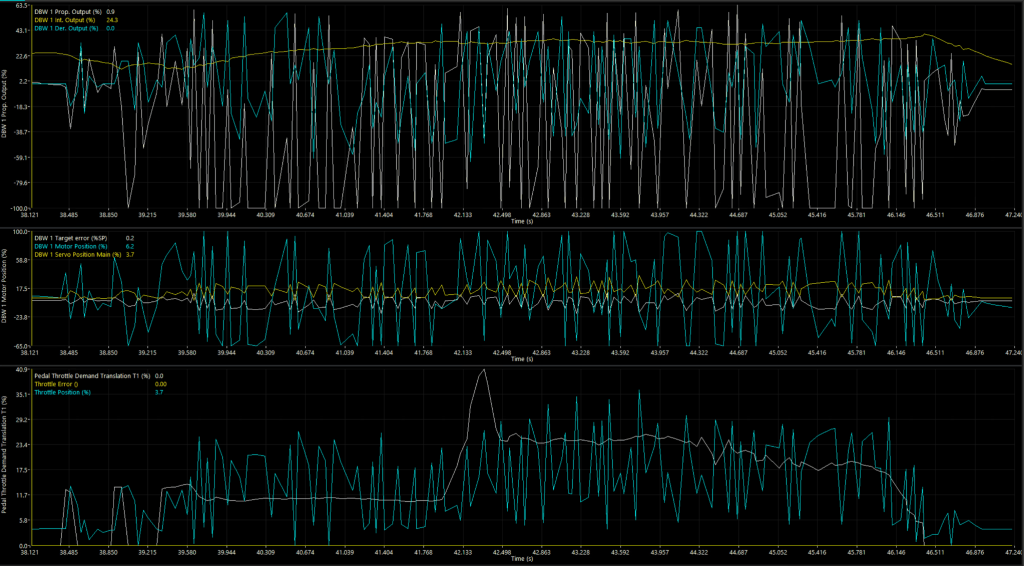
Proportional output is saturating at minus 100 percent repeatedly, and topping out near plus 63. That asymmetry is not the axis autoscaling being unhelpful. It is the loop reaching its closing clamp over and over while never reaching the opening one.
Integral output is sitting around plus 24 percent and climbing slowly across the window. An integrator that keeps accumulating while the proportional term is pinned at its clamp is not doing the job an integrator is for.
The motor command is swinging roughly minus 65 to plus 100 percent while the measured blade position only moves a few percent either side of 15. The blade is inertially filtered. It physically cannot follow a command oscillating at that rate, so the engine never sees the full excursion.
That last point is the one that connects back to the shift. The engine does not see it, but the model does. Torque estimate comes from air mass, air mass in this region comes from the throttle mass flow model, and that model reads blade position directly. Every percent of blade wobble goes into the torque estimate whether or not the engine produced any of it.
The gearbox was reacting to torque noise that did not exist at the crankshaft.
The arithmetic
Status: Verified
This is where the log stops being suggestive and starts being conclusive. At the cursor, 38.138s in the screenshot above:
- Servo Position Main: 3.7 percent
- Proportional output: 0.9 percent
- Integral output: 24.3 percent
- Derivative output: 0.0 percent
- Motor command: 6.2 percent
My feed-forward table runs minus 30 at 0 percent and minus 15 at 5 percent. Interpolated linearly, feed-forward at 3.7 percent is minus 18.9.
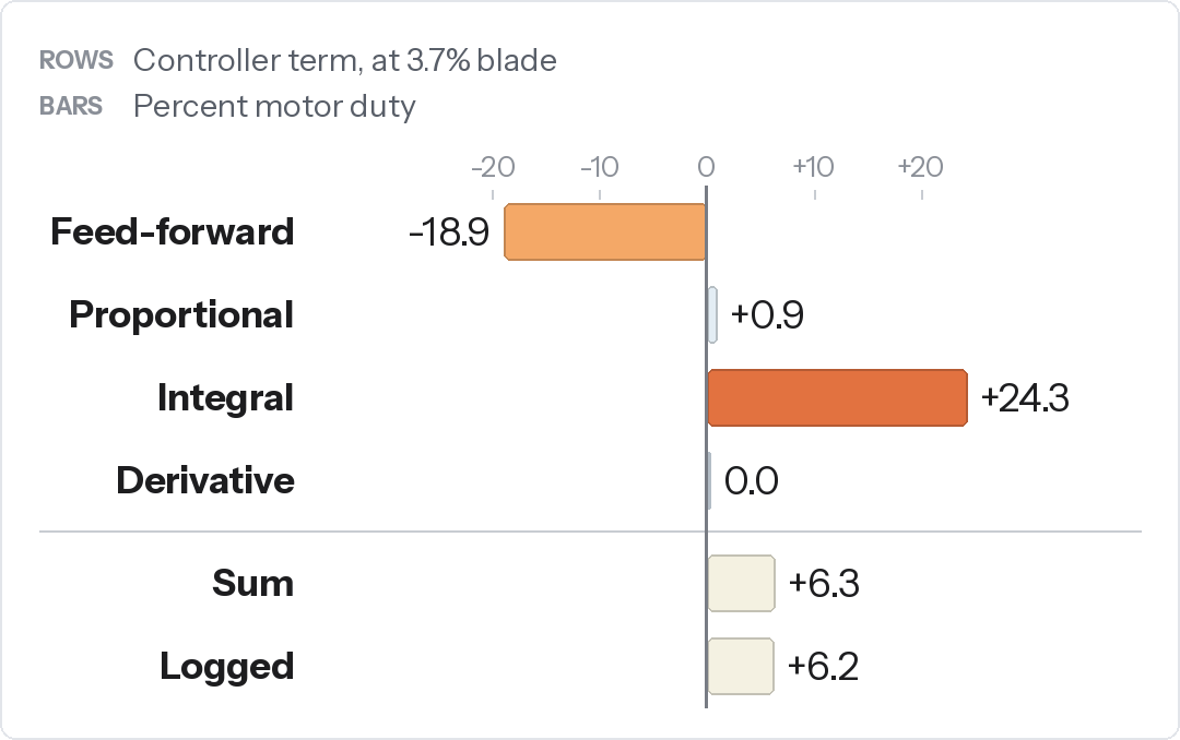
Two things fall out of a match that close. Motor command is the summed controller output rather than a measured position, and feed-forward interpolates linearly between breakpoints.
But the finding is the third thing. At a near steady 3.7 percent blade position, the integral had wound to plus 24.3 for no purpose other than to cancel a feed-forward of minus 18.9.
The feed-forward in the 0 to 5 percent band is asking for roughly 25 points of closing duty that the throttle body does not need. The integral is spending its entire authority undoing it. That is a large stored state sitting permanently in the loop, and every time the proportional term saturates and the target moves, that state has to unwind before anything else can settle.
It is a far better explanation for a sustained oscillation than any single gain cell.
The feed-forward step, and what it actually is
Status: Provisional
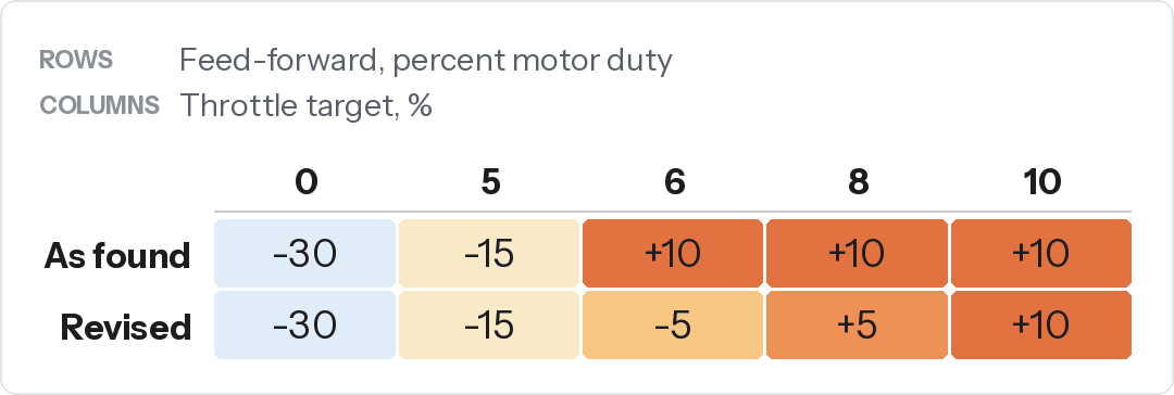
There is a 25 point change in motor duty for a 1 percent movement in target between 5 and 6 percent, and the log crosses that region immediately before one of the instabilities. My first instinct was that this was simply wrong. It is not, and this is the part most likely to be copied badly, so it is worth saying plainly.
The return spring on a DBW body pulls the blade towards its limp home position from both directions. Below limp home you need negative duty to hold the blade down against the spring. Above it you need positive duty to hold it open. A feed-forward table that changes sign between two cells is not a tuning error. It is the table telling you where limp home sits.
Delete the step and you have not removed the discontinuity. You have removed the compensation for it, and handed the spring preload to the integrator.
The real problems are different. First, the magnitude of the low band values, which the arithmetic above says are too negative. Second, a 25 point change interpolated across 1 percent of travel behaves like a gain of 25 through a region the blade is oscillating in.
The proportional gain table
Status: Provisional
The low position P gains are aggressive, and lopsided towards the negative error side.
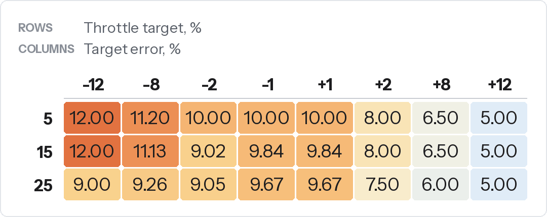
Reading negative error as blade above target, the closing correction gets close to twice the gain available for an equivalent opening error, at every row.
The spring makes this more interesting than a simple symmetry argument, because the asymmetry it creates flips across limp home. Above limp home the spring already assists closing, so the loop needs more authority to open and less to close. Below limp home it reverses.
A table that favours the closing side at every row is therefore directionally right in the 5 percent row and wrong in the 15 and 25 percent rows. The blade sits at 15 to 17 percent through this event.
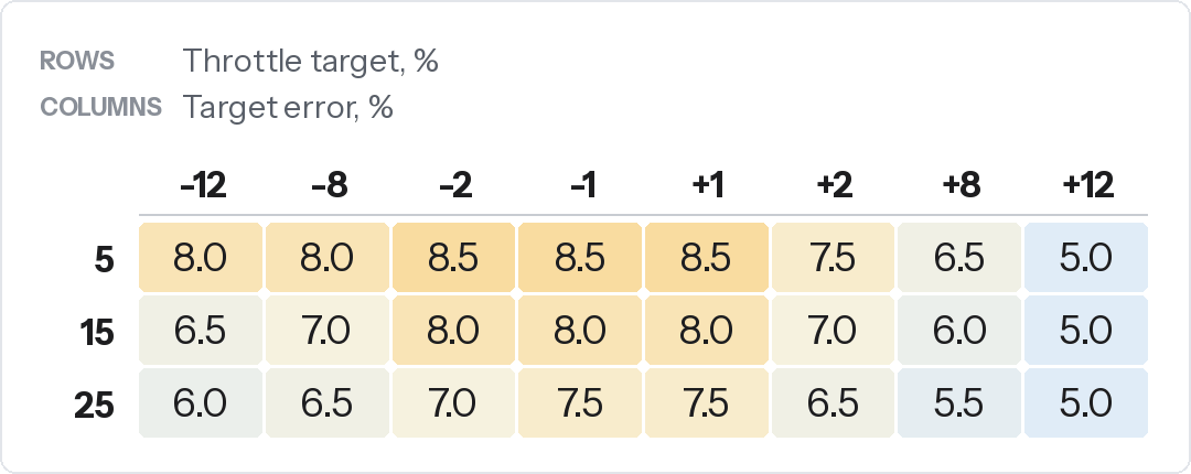
One caveat that anyone copying this needs to take seriously. The whole reading above depends on the error channel being target minus actual. If your ECU signs it the other way, the argument inverts and so does the revision. Confirm it on your own log before you touch a cell: find a step where the blade visibly lags a rising target, and read the sign.
What I have not proved yet
I changed two tables at once. Until they are separated, no outcome can be attributed to either.
I have not measured the true limp home position. The right way is to unpower the driver and read the TPS, then check whether the feed-forward breakpoints actually straddle it. If limp home sits at 6.5 percent rather than between 5 and 6, the compensation is being applied in the wrong place, and that alone would explain the instability without a single gain change.
I have not confirmed the error sign convention from a step.
And I left the 0 and 5 percent feed-forward cells alone, which are the two cells the arithmetic actually points at.
I’m not declaring this as “fixed” yet. However, the gear change is smoother, particularly the upshift. The lower speed acceleration is cleaner and everything just feels much more refined. Always remember the first few percent of opening on a throttle blade are extremely non-linear, and even more so on a 82mm throttle body.
The test that closes it
With the loop stable, park the blade at steady positions across 0 to 25 percent, in 2 percent steps through the 0 to 8 percent band, and log feed-forward and integral at each point.
Wherever the integral is non-zero at steady state, the feed-forward is wrong by exactly that amount. That lets the whole low band feed-forward table be built by subtraction rather than by iteration. The position at which feed-forward crosses zero and the integral stays at zero is the true limp home. Any step within the sweep settles the sign convention.
Run it on the same road and the same coast down and you also get a genuinely matched before and after, rather than two logs taken a week apart under different load.
The principle
The data is not transferable, but the principle is.
A feed-forward table and an integrator are solving the same problem from opposite ends. If the integrator is carrying a large standing value at a steady operating point, the feed-forward is wrong by that amount, and you can read the correction straight off the log instead of iterating towards it.
The throttle area table that the whole torque model sits on is covered in Throttle Body Effective Flow Area, and the same feed-forward versus PID argument applied to traction control is in Traction Control on 1,114 whp. Full specification is on the Supra project page.
If you run a DBW loop and have taken a different view on any of this, particularly the limp home reasoning or the gain asymmetry, I would like to hear it.